

Zie specificaties voor productdetails.
TDC1011PWR
Product Overview
Category
TDC1011PWR belongs to the category of integrated circuits (ICs).
Use
The TDC1011PWR is primarily used for time-to-digital conversion applications.
Characteristics
- High precision time measurement
- Low power consumption
- Small form factor
- Wide operating voltage range
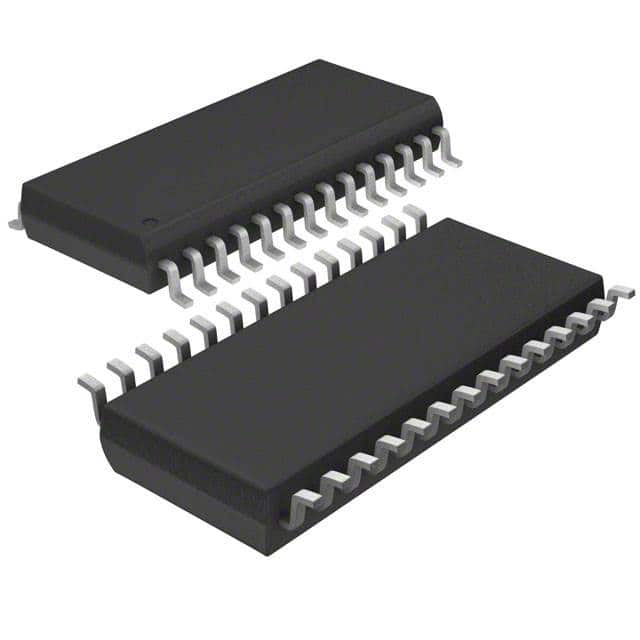
Package
TDC1011PWR is available in a small outline package (SOP) with a specified pin configuration.
Essence
The essence of TDC1011PWR lies in its ability to accurately measure time intervals and convert them into digital data.
Packaging/Quantity
The TDC1011PWR is typically packaged in reels, containing a specific quantity of ICs per reel.
Specifications
- Supply Voltage: 2.7V to 3.6V
- Operating Temperature Range: -40°C to +85°C
- Resolution: 10 ps
- Conversion Time: 20 ns
- Input Signal Range: 0V to VDD
- Output Data Format: Binary or BCD
Detailed Pin Configuration
The TDC1011PWR has the following pin configuration:
- VDD: Power supply input
- GND: Ground reference
- START: Start signal input
- STOP: Stop signal input
- CLK: Clock signal input
- DATA: Digital output data
- REF: Reference clock input
- TEST: Test mode selection input
Functional Features
- High-resolution time-to-digital conversion
- Adjustable conversion range
- Internal clock generator
- Built-in test mode for calibration and diagnostics
- Low power consumption
Advantages and Disadvantages
Advantages
- High precision time measurement
- Compact size
- Wide operating voltage range
- Low power consumption
Disadvantages
- Limited conversion time
- Requires external clock signal
Working Principles
The TDC1011PWR operates based on the principle of measuring the time difference between a start and stop signal. It utilizes an internal clock to accurately measure the time interval and converts it into digital data.
Detailed Application Field Plans
The TDC1011PWR finds applications in various fields, including:
- Distance measurement systems
- Time-of-flight (TOF) cameras
- Laser range finders
- Ultrasonic flow meters
- Radar systems
Detailed and Complete Alternative Models
- TDC1012PWR: Similar to TDC1011PWR with extended features.
- TDC1013PWR: Higher resolution version of TDC1011PWR.
- TDC1014PWR: Enhanced performance variant with additional functionalities.
These alternative models offer similar functionality but may have different specifications or additional features.
In conclusion, the TDC1011PWR is a high-precision integrated circuit used for time-to-digital conversion applications. Its compact size, low power consumption, and wide operating voltage range make it suitable for various fields such as distance measurement systems, TOF cameras, and radar systems. While it has advantages like high precision and small form factor, it also has limitations such as limited conversion time and the need for an external clock signal. Alternative models like TDC1012PWR, TDC1013PWR, and TDC1014PWR provide options with enhanced features or improved performance.
Noem 10 veelgestelde vragen en antwoorden met betrekking tot de toepassing van TDC1011PWR in technische oplossingen
Sure! Here are 10 common questions and answers related to the application of TDC1011PWR in technical solutions:
Q1: What is TDC1011PWR? A1: TDC1011PWR is a time-to-digital converter (TDC) integrated circuit that converts time intervals into digital data.
Q2: What is the operating voltage range of TDC1011PWR? A2: The operating voltage range of TDC1011PWR is typically between 2.7V and 3.6V.
Q3: What is the resolution of TDC1011PWR? A3: TDC1011PWR has a resolution of 10 ps, which means it can measure time intervals with a precision of 10 picoseconds.
Q4: What is the maximum input frequency supported by TDC1011PWR? A4: TDC1011PWR supports a maximum input frequency of 100 MHz.
Q5: Can TDC1011PWR be used for distance measurement applications? A5: Yes, TDC1011PWR can be used for distance measurement applications as it accurately measures time intervals, which can be converted into distance measurements.
Q6: Does TDC1011PWR have any built-in calibration features? A6: No, TDC1011PWR does not have any built-in calibration features. External calibration may be required for accurate measurements.
Q7: What is the output format of TDC1011PWR? A7: TDC1011PWR provides a digital output in the form of a serial interface (SPI) or a parallel interface.
Q8: Can TDC1011PWR be used in battery-powered applications? A8: Yes, TDC1011PWR can be used in battery-powered applications as it operates within a low voltage range and has low power consumption.
Q9: What is the typical accuracy of TDC1011PWR? A9: The typical accuracy of TDC1011PWR is around 1% of the measured time interval.
Q10: Are there any evaluation boards available for TDC1011PWR? A10: Yes, Texas Instruments provides an evaluation module (EVM) for TDC1011PWR, which can be used for testing and development purposes.
Please note that these answers are general and may vary depending on the specific application and implementation of TDC1011PWR.