

Zie specificaties voor productdetails.
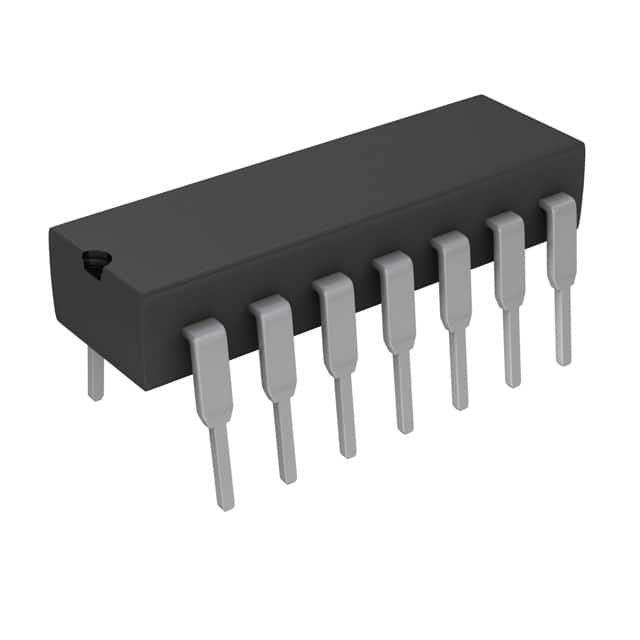
SN74AS74AN
Product Overview
- Category: Integrated Circuit (IC)
- Use: Flip-Flop
- Characteristics: Dual D-Type Positive-Edge-Triggered Flip-Flop
- Package: PDIP-14 (Plastic Dual-In-Line Package with 14 pins)
- Essence: The SN74AS74AN is a dual flip-flop IC that can store and transfer binary data.
- Packaging/Quantity: Typically sold in reels or tubes containing multiple units.
Specifications
- Supply Voltage Range: 4.5V to 5.5V
- High-Level Input Voltage: 2.0V (min), 7.0V (max)
- Low-Level Input Voltage: -0.5V (min), 0.8V (max)
- High-Level Output Voltage: 2.4V (min), VCC (max)
- Low-Level Output Voltage: 0V (min), 0.4V (max)
- Maximum Operating Frequency: 100MHz
Detailed Pin Configuration
The SN74AS74AN has a total of 14 pins, which are assigned specific functions as follows:
- CLR (Clear) - Active LOW input for clearing the flip-flop.
- D1 (Data Input 1) - Data input for the first flip-flop.
- CLK (Clock) - Input for clock signal triggering the flip-flop.
- D2 (Data Input 2) - Data input for the second flip-flop.
- Q1 (Output 1) - Output of the first flip-flop.
- Q1' (Complementary Output 1) - Complementary output of the first flip-flop.
- GND (Ground) - Ground reference for the IC.
- Q2' (Complementary Output 2) - Complementary output of the second flip-flop.
- Q2 (Output 2) - Output of the second flip-flop.
- PRE (Preset) - Active LOW input for presetting the flip-flop.
- PRD (Preset Disable) - Active HIGH input for disabling the preset function.
- CLR' (Complementary Clear) - Complementary output of the clear input.
- VCC (Positive Power Supply) - Positive power supply for the IC.
- PRD' (Complementary Preset Disable) - Complementary output of the preset disable input.
Functional Features
- Dual D-Type Flip-Flop: The SN74AS74AN consists of two independent D-type flip-flops, allowing for simultaneous storage and transfer of data.
- Positive-Edge Triggered: The flip-flop triggers on the rising edge of the clock signal, ensuring accurate data capture.
- Asynchronous Clear and Preset: The IC provides inputs for clearing and presetting the flip-flop asynchronously, allowing for flexible control.
- Complementary Outputs: The complementary outputs provide inverted versions of the main outputs, enabling versatile logic operations.
Advantages and Disadvantages
Advantages: - Dual flip-flop design allows for efficient use of space and resources. - Positive-edge triggering ensures reliable data capture. - Asynchronous clear and preset inputs offer flexibility in controlling the flip-flop's state. - Complementary outputs enable a wider range of logic operations.
Disadvantages: - Limited operating frequency compared to more advanced flip-flop designs. - Requires external components for proper functioning, such as clock signal source.
Working Principles
The SN74AS74AN operates based on the principles of sequential logic. It uses positive-edge triggering to latch and store data at the rising edge of the clock signal. The stored data can then be transferred to the outputs upon receiving a clock pulse. The asynchronous clear and preset inputs allow for immediate resetting or setting of the flip-flop's state, regardless of the clock signal.
Detailed Application Field Plans
The SN74AS74AN is commonly used in various digital systems and applications, including:
- Counters and Registers: The dual flip-flop design makes it suitable for building counters and registers that require multiple storage elements.
- Data Synchronization: It can be used to synchronize data between different parts of a system, ensuring proper timing and avoiding data corruption.
- State Machines: The flip-flop can be utilized in designing state machines, where sequential logic is required to control system behavior based on specific conditions.
- Clock Division: By utilizing one of the flip-flops as a divide-by-two circuit, the IC can generate lower-frequency clock signals from a higher-frequency input.
Detailed and Complete Alternative Models
- SN7474: Dual D-Type Positive-Edge-Triggered Flip-Flop with Preset and Clear
- CD4013B: CMOS Dual D-Type Flip-Flop
- MC74HC74A: High-Speed CMOS Logic Dual D-Type Flip-Flop
Noem 10 veelgestelde vragen en antwoorden met betrekking tot de toepassing van SN74AS74AN in technische oplossingen
Sure! Here are 10 common questions and answers related to the application of SN74AS74AN in technical solutions:
Q: What is SN74AS74AN? A: SN74AS74AN is a dual D-type flip-flop integrated circuit (IC) that can store and manipulate digital signals.
Q: What are the key features of SN74AS74AN? A: Some key features include dual D-type flip-flops, asynchronous clear inputs, and positive-edge-triggered clock inputs.
Q: How can SN74AS74AN be used in technical solutions? A: SN74AS74AN can be used for various applications such as data storage, frequency division, and synchronization in digital systems.
Q: What is the operating voltage range for SN74AS74AN? A: The operating voltage range for SN74AS74AN is typically between 4.5V and 5.5V.
Q: Can SN74AS74AN handle high-speed operations? A: Yes, SN74AS74AN is designed to operate at high speeds, making it suitable for applications that require fast data processing.
Q: Does SN74AS74AN have any built-in protection features? A: No, SN74AS74AN does not have built-in protection features. It is important to ensure proper voltage levels and signal conditioning to prevent damage.
Q: How many flip-flops are there in SN74AS74AN? A: SN74AS74AN contains two independent D-type flip-flops, allowing for simultaneous operation or separate functionality.
Q: Can SN74AS74AN be cascaded to create larger counters or shift registers? A: Yes, multiple SN74AS74AN ICs can be cascaded together to create larger counters or shift registers, expanding their functionality.
Q: What is the maximum clock frequency for SN74AS74AN? A: The maximum clock frequency for SN74AS74AN is typically around 100 MHz, but it may vary depending on the specific operating conditions.
Q: Are there any recommended external components to use with SN74AS74AN? A: It is generally recommended to use decoupling capacitors near the power supply pins of SN74AS74AN to minimize noise and ensure stable operation.
Please note that these answers are general and may vary based on specific application requirements and datasheet specifications.