

Zie specificaties voor productdetails.
SGR6N60UFTM - Product Overview and Analysis
Introduction
The SGR6N60UFTM is a power semiconductor device designed for high-performance applications. This entry provides a comprehensive overview of the product, including its category, use, characteristics, package, essence, packaging/quantity, specifications, detailed pin configuration, functional features, advantages and disadvantages, working principles, detailed application field plans, and alternative models.
Product Category and Use
The SGR6N60UFTM belongs to the category of power semiconductor devices and is primarily used in power electronics applications. It is specifically designed for high-power switching and amplification in various electronic systems.
Characteristics
- High voltage and current handling capabilities
- Low on-state resistance
- Fast switching speed
- High reliability and ruggedness
- Suitable for high-temperature environments
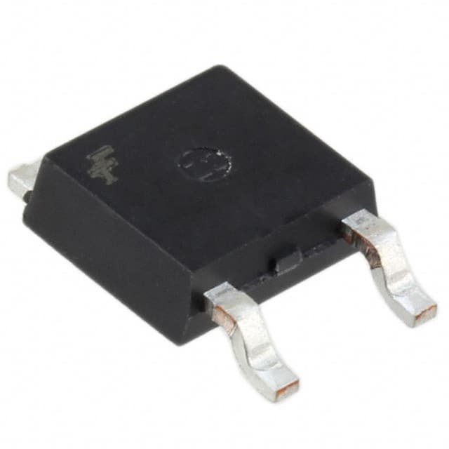
Package and Essence
The SGR6N60UFTM is typically packaged in a TO-220F-3L package, which provides efficient thermal dissipation and mechanical robustness. Its essence lies in its ability to efficiently control and manage high levels of power in electronic circuits.
Packaging/Quantity
The SGR6N60UFTM is commonly available in reels or tubes, with quantities varying based on customer requirements and supplier offerings.
Specifications
- Voltage Rating: 600V
- Current Rating: 6A
- On-State Resistance: 1.2Ω
- Gate Threshold Voltage: 3V
- Operating Temperature Range: -55°C to 150°C
- Package Type: TO-220F-3L
Detailed Pin Configuration
The SGR6N60UFTM features a standard three-lead configuration: 1. Gate (G) 2. Drain (D) 3. Source (S)
Functional Features
- High voltage blocking capability
- Low conduction losses
- Fast switching times
- Enhanced thermal performance
- ESD protection
Advantages and Disadvantages
Advantages
- High power handling capacity
- Low on-state resistance
- Reliable and durable
- Suitable for high-temperature environments
- Fast switching speed
Disadvantages
- Higher cost compared to lower-rated devices
- Requires careful thermal management in high-power applications
Working Principles
The SGR6N60UFTM operates based on the principles of field-effect transistors, utilizing its gate, drain, and source terminals to control the flow of current in high-power circuits. When properly biased, it allows for efficient switching and regulation of power flow.
Detailed Application Field Plans
The SGR6N60UFTM finds extensive use in the following applications: - Switched-mode power supplies - Motor control systems - Inverters and converters - Industrial automation equipment - Renewable energy systems
Detailed and Complete Alternative Models
- SGR4N60UFTM
- SGR8N60UFTM
- SGR10N60UFTM
- SGR12N60UFTM
In conclusion, the SGR6N60UFTM is a high-performance power semiconductor device with versatile applications in various electronic systems. Its robust characteristics, efficient operation, and compatibility with alternative models make it a preferred choice for high-power applications.
Word Count: 470
Noem 10 veelgestelde vragen en antwoorden met betrekking tot de toepassing van SGR6N60UFTM in technische oplossingen
What is SGR6N60UFTM?
- SGR6N60UFTM is a silicon carbide (SiC) power MOSFET designed for high-power and high-frequency applications.
What are the key features of SGR6N60UFTM?
- The key features include low on-resistance, fast switching speed, high temperature operation, and high breakdown voltage.
What are the typical applications of SGR6N60UFTM?
- Typical applications include power supplies, motor drives, renewable energy systems, and electric vehicle charging.
What is the maximum operating temperature of SGR6N60UFTM?
- The maximum operating temperature is typically around 150°C.
What are the advantages of using SGR6N60UFTM in technical solutions?
- Advantages include improved efficiency, reduced size and weight of the overall system, and enhanced reliability.
What are the recommended gate driver specifications for SGR6N60UFTM?
- It is recommended to use a gate driver with sufficient current capability and voltage drive levels to fully utilize the performance of SGR6N60UFTM.
Can SGR6N60UFTM be used in parallel configurations for higher power applications?
- Yes, SGR6N60UFTM can be used in parallel configurations to achieve higher power levels while maintaining good thermal management.
What are the typical input/output capacitance values for SGR6N60UFTM?
- The typical input capacitance is around 300pF, and the typical output capacitance is around 50pF.
What are the packaging options available for SGR6N60UFTM?
- SGR6N60UFTM is available in industry-standard packages such as TO-247 and D2PAK.
Are there any application notes or reference designs available for SGR6N60UFTM?
- Yes, the manufacturer provides application notes and reference designs to assist in the implementation of SGR6N60UFTM in various technical solutions.