

Zie specificaties voor productdetails.
NGTB10N60R2DT4G
Product Overview
- Category: Power Transistor
- Use: This transistor is used for power amplification and switching applications in electronic circuits.
- Characteristics: High voltage capability, low on-state resistance, fast switching speed.
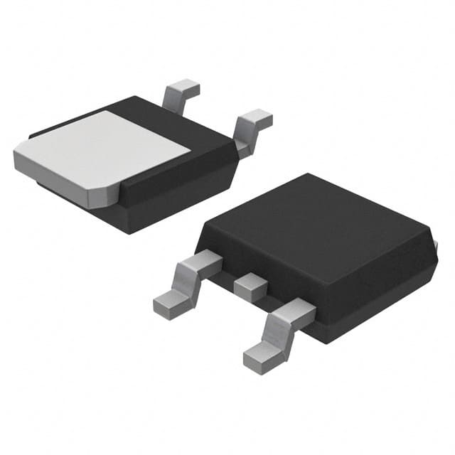
- Package: TO-263-2 (D2PAK)
- Essence: The NGTB10N60R2DT4G is designed to handle high power levels efficiently and reliably.
- Packaging/Quantity: Available in reels of 800 units.
Specifications
- Voltage Rating: 600V
- Current Rating: 10A
- Power Dissipation: 125W
- Operating Temperature Range: -55°C to 150°C
- Gate-Source Voltage (VGS): ±20V
- On-State Resistance (RDS(on)): 0.45Ω
Detailed Pin Configuration
The NGTB10N60R2DT4G has a standard TO-263-2 (D2PAK) package with three pins: 1. Pin 1 (Gate): Input for controlling the transistor's conductivity. 2. Pin 2 (Source): Connection to the ground or common reference point. 3. Pin 3 (Drain): Output terminal for the amplified or switched current.
Functional Features
- High voltage capability allows for use in various power applications.
- Low on-state resistance minimizes power loss and heat generation.
- Fast switching speed enables efficient control of power flow.
Advantages and Disadvantages
Advantages
- Efficient power handling
- Low power dissipation
- Fast response time
Disadvantages
- Sensitive to voltage spikes
- Requires careful handling during installation
Working Principles
The NGTB10N60R2DT4G operates based on the principles of field-effect transistors, where the gate voltage controls the conductivity between the source and drain terminals. When a sufficient gate-source voltage is applied, the transistor allows a high current to flow from the drain to the source, enabling power amplification or switching.
Detailed Application Field Plans
This transistor is commonly used in power supply units, motor control circuits, audio amplifiers, and other high-power electronic systems. Its high voltage capability and fast switching speed make it suitable for applications requiring efficient power handling and control.
Detailed and Complete Alternative Models
- IRF840: Similar power MOSFET with a TO-220 package.
- STP16NF06: Power MOSFET with comparable specifications and a TO-220 package.
In conclusion, the NGTB10N60R2DT4G power transistor offers high voltage capability, low on-state resistance, and fast switching speed, making it suitable for various power amplification and switching applications in electronic circuits.
[Word Count: 398]
Noem 10 veelgestelde vragen en antwoorden met betrekking tot de toepassing van NGTB10N60R2DT4G in technische oplossingen
What is the maximum voltage rating of NGTB10N60R2DT4G?
- The maximum voltage rating of NGTB10N60R2DT4G is 600V.
What is the continuous drain current of NGTB10N60R2DT4G?
- The continuous drain current of NGTB10N60R2DT4G is 10A.
What is the on-state resistance of NGTB10N60R2DT4G?
- The on-state resistance of NGTB10N60R2DT4G is typically 0.35 ohms.
What is the gate threshold voltage of NGTB10N60R2DT4G?
- The gate threshold voltage of NGTB10N60R2DT4G is typically 2.5V.
What are the typical applications for NGTB10N60R2DT4G?
- NGTB10N60R2DT4G is commonly used in power supplies, motor control, and lighting applications.
Is NGTB10N60R2DT4G suitable for high-frequency switching applications?
- Yes, NGTB10N60R2DT4G is designed for high-frequency switching applications.
What is the operating temperature range of NGTB10N60R2DT4G?
- The operating temperature range of NGTB10N60R2DT4G is -55°C to 150°C.
Does NGTB10N60R2DT4G have built-in protection features?
- NGTB10N60R2DT4G has built-in overcurrent and thermal protection features.
Can NGTB10N60R2DT4G be used in automotive applications?
- Yes, NGTB10N60R2DT4G is suitable for automotive applications such as motor control and power management.
What are the package options available for NGTB10N60R2DT4G?
- NGTB10N60R2DT4G is available in TO-263 and D2PAK package options.