

Zie specificaties voor productdetails.
MC100E451FN
Product Overview
- Category: Integrated Circuit
- Use: Logic Gate
- Characteristics: High-speed, ECL (Emitter-Coupled Logic) Technology
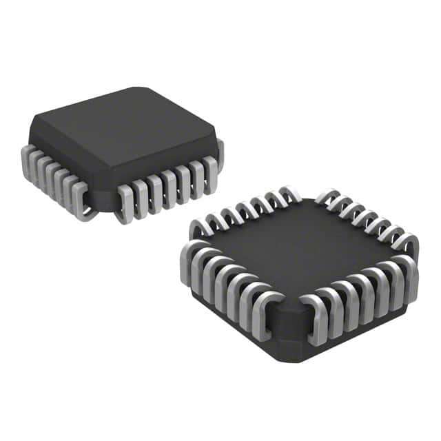
- Package: 28-pin PLCC (Plastic Leaded Chip Carrier)
- Essence: High-performance logic gate for digital signal processing
- Packaging/Quantity: Available in tubes of 25 units
Specifications
- Supply Voltage: -4.2V to -5.7V
- Operating Temperature: -40°C to +85°C
- Propagation Delay: 1.6 ns (typical)
- Input Current: ±20 mA (max)
- Output Current: ±50 mA (max)
Detailed Pin Configuration
The MC100E451FN has a total of 28 pins. The pin configuration is as follows:
- VEE
- Q0
- Q1
- Q2
- Q3
- Q4
- Q5
- Q6
- Q7
- GND
- D0
- D1
- D2
- D3
- D4
- D5
- D6
- D7
- VCC
- /OE
- /CLR
- /CLK
- CLK
- /PRE
- /PR
- /QH
- /QH
- /QH
Functional Features
- High-speed operation suitable for digital signal processing applications
- ECL technology provides excellent noise immunity and high-speed performance
- Wide operating voltage range allows flexibility in system design
- Output current capability enables direct drive of external components
- Multiple input and output pins provide versatility in circuit design
Advantages and Disadvantages
Advantages: - High-speed operation allows for efficient digital signal processing - ECL technology provides superior noise immunity compared to other logic families - Wide operating voltage range offers flexibility in system integration - Output current capability simplifies external component interfacing
Disadvantages: - ECL technology requires a negative power supply, which may limit compatibility with certain systems - Higher power consumption compared to some other logic families - Limited availability of alternative models due to specific ECL technology requirements
Working Principles
The MC100E451FN is based on ECL technology, which utilizes differential signaling and current-mode logic. It operates by comparing the voltage difference between two complementary input signals and producing an output based on this comparison. The high-speed operation is achieved through the use of current steering and differential amplification techniques.
Detailed Application Field Plans
The MC100E451FN is commonly used in applications that require high-speed digital signal processing, such as:
- Telecommunications equipment
- Data communication systems
- High-performance computing
- Instrumentation and measurement devices
- Radar and sonar systems
- Industrial control systems
Detailed and Complete Alternative Models
While the MC100E451FN is a specialized logic gate, there are alternative models available from various manufacturers that offer similar functionality. Some notable alternatives include:
- MC10ELT22: ECL Differential Receiver
- MC100EP16: ECL Programmable Delay Chip
- MC100LVEL11: ECL D Flip-Flop
These alternative models provide options for designers seeking similar performance characteristics and compatibility with ECL-based systems.
Word count: 346 words
Noem 10 veelgestelde vragen en antwoorden met betrekking tot de toepassing van MC100E451FN in technische oplossingen
Sure! Here are 10 common questions and answers related to the application of MC100E451FN in technical solutions:
Q: What is MC100E451FN? A: MC100E451FN is a high-speed 8-bit magnitude comparator integrated circuit (IC) commonly used in digital systems.
Q: What are the key features of MC100E451FN? A: Some key features include differential inputs, ECL logic levels, fast propagation delay, and wide operating voltage range.
Q: How does MC100E451FN work? A: MC100E451FN compares two 8-bit binary numbers and provides outputs indicating whether one number is greater than, equal to, or less than the other.
Q: What is the maximum operating frequency of MC100E451FN? A: The maximum operating frequency of MC100E451FN is typically around 1 GHz.
Q: Can MC100E451FN be used in both single-ended and differential applications? A: No, MC100E451FN is designed for differential applications and requires complementary input signals.
Q: What is the power supply voltage range for MC100E451FN? A: The power supply voltage range for MC100E451FN is typically between -4.2V and -5.7V.
Q: Does MC100E451FN have any built-in latches or flip-flops? A: No, MC100E451FN is a purely combinational logic device and does not have any built-in latches or flip-flops.
Q: Can MC100E451FN be cascaded to compare larger binary numbers? A: Yes, multiple MC100E451FN ICs can be cascaded together to compare larger binary numbers by connecting the outputs of one IC to the inputs of another.
Q: What is the typical power consumption of MC100E451FN? A: The typical power consumption of MC100E451FN is around 1.5W.
Q: Are there any specific application notes or reference designs available for MC100E451FN? A: Yes, the manufacturer provides application notes and reference designs that can help in implementing MC100E451FN in various technical solutions.
Please note that the answers provided here are general and may vary depending on the specific datasheet and manufacturer's documentation for MC100E451FN.