

Zie specificaties voor productdetails.
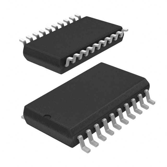
74F579SJ
Product Overview
- Category: Integrated Circuit (IC)
- Use: Data storage and retrieval
- Characteristics: High-speed, low-power consumption
- Package: Dual in-line package (DIP)
- Essence: Flip-flop register
- Packaging/Quantity: Available in reels of 250 units
Specifications
- Technology: CMOS
- Supply Voltage: 4.5V to 5.5V
- Operating Temperature: -40°C to +85°C
- Input/Output Compatibility: TTL
- Clock Frequency: Up to 100 MHz
- Number of Bits: 8
- Logic Family: 74F
Detailed Pin Configuration
The 74F579SJ IC has a total of 20 pins, which are assigned as follows:
- D0: Data input bit 0
- D1: Data input bit 1
- D2: Data input bit 2
- D3: Data input bit 3
- D4: Data input bit 4
- D5: Data input bit 5
- D6: Data input bit 6
- D7: Data input bit 7
- GND: Ground
- Q0: Output bit 0
- Q1: Output bit 1
- Q2: Output bit 2
- Q3: Output bit 3
- Q4: Output bit 4
- Q5: Output bit 5
- Q6: Output bit 6
- Q7: Output bit 7
- OE: Output enable
- CLK: Clock input
- VCC: Power supply
Functional Features
- The 74F579SJ is an 8-bit flip-flop register that can store and retrieve data.
- It operates at high speeds, making it suitable for applications requiring rapid data processing.
- The IC has low power consumption, making it energy-efficient.
- The output enable (OE) pin allows for easy control of the output state.
- The clock input (CLK) synchronizes the data transfer within the register.
Advantages and Disadvantages
Advantages: - High-speed operation enables efficient data processing. - Low power consumption reduces energy usage. - Versatile and widely used in various applications. - Easy to control the output state using the OE pin.
Disadvantages: - Limited number of bits (8) may not be sufficient for certain applications requiring larger data storage.
Working Principles
The 74F579SJ operates based on flip-flop technology. When the clock signal is applied, the data present at the input pins (D0-D7) is transferred to the corresponding output pins (Q0-Q7). The output enable (OE) pin controls whether the output is active or in a high-impedance state.
Detailed Application Field Plans
The 74F579SJ is commonly used in the following applications:
- Microcontrollers: Used as a temporary storage unit for data during processing.
- Communication Systems: Facilitates data transmission and reception.
- Data Acquisition Systems: Stores sampled data for further analysis.
- Digital Signal Processing: Enables efficient manipulation of digital signals.
- Memory Addressing: Utilized for addressing memory locations in computer systems.
Detailed and Complete Alternative Models
- 74HC579: Similar functionality with improved power efficiency.
- 74LS579: Lower power consumption but slower operation speed.
- 74ACT579: Faster operation speed with higher power consumption.
- 74LVC579: Reduced voltage swing for lower power dissipation.
Note: These alternative models may have different pin configurations and specifications. It is important to refer to their respective datasheets for detailed information.
Word count: 411 words
Noem 10 veelgestelde vragen en antwoorden met betrekking tot de toepassing van 74F579SJ in technische oplossingen
Sure! Here are 10 common questions and answers related to the application of 74F579SJ in technical solutions:
Q: What is the 74F579SJ? A: The 74F579SJ is a 8-bit transparent latch with 3-state outputs, commonly used in digital circuits.
Q: What is the purpose of using the 74F579SJ in a circuit? A: The 74F579SJ can be used to store and hold data temporarily, allowing for sequential operations in digital systems.
Q: How many bits can the 74F579SJ latch hold? A: The 74F579SJ can hold 8 bits of data.
Q: What is the difference between a transparent latch and a flip-flop? A: Unlike a flip-flop, a transparent latch allows the input to pass through to the output when the latch enable signal is active.
Q: How does the 74F579SJ handle multiple latches in a circuit? A: Multiple 74F579SJ latches can be cascaded together to create larger storage capacities.
Q: Can the 74F579SJ drive other devices directly? A: No, the 74F579SJ requires additional buffer or driver circuits to drive external devices.
Q: What is the maximum clock frequency supported by the 74F579SJ? A: The maximum clock frequency depends on various factors, but typically it can operate at frequencies up to several tens of megahertz.
Q: Can the 74F579SJ be used in both synchronous and asynchronous applications? A: Yes, the 74F579SJ can be used in both synchronous and asynchronous applications depending on how the latch enable signal is controlled.
Q: What is the power supply voltage range for the 74F579SJ? A: The 74F579SJ typically operates with a power supply voltage range of 4.5V to 5.5V.
Q: Are there any specific precautions to consider when using the 74F579SJ? A: It is important to ensure proper decoupling and bypass capacitors are used to minimize noise and stabilize the power supply. Additionally, care should be taken to avoid exceeding the maximum ratings specified in the datasheet.
Please note that these answers are general and may vary depending on the specific application and circuit design.