

Zie specificaties voor productdetails.
Encyclopedia Entry: 74AC109SJ
Product Overview
Category
The 74AC109SJ belongs to the category of integrated circuits (ICs) and specifically falls under the family of flip-flops.
Use
This IC is commonly used in digital electronic circuits for storing and manipulating binary data. It serves as a dual positive-edge triggered JK flip-flop with clear functionality.
Characteristics
- Dual JK flip-flop with clear
- Positive-edge triggered
- High-speed operation
- Low power consumption
- Wide operating voltage range
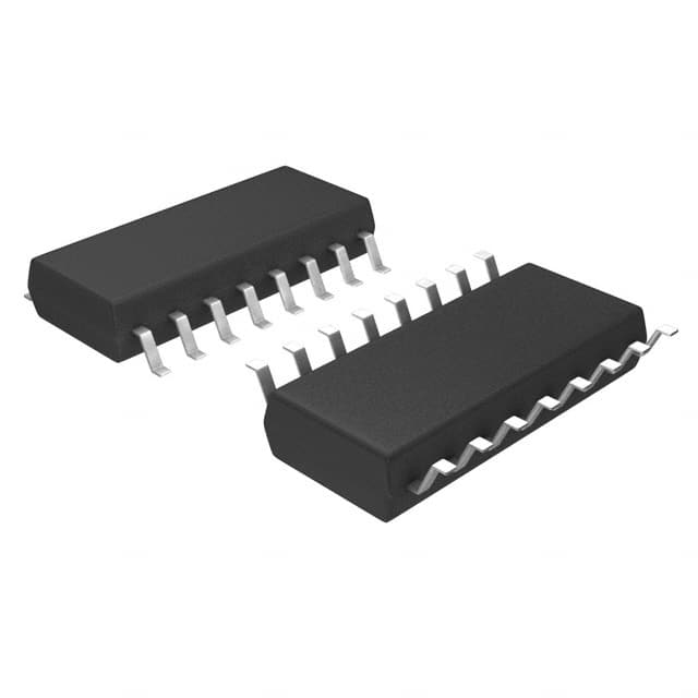
Package
The 74AC109SJ is available in a small outline integrated circuit (SOIC) package, which provides ease of handling and compatibility with various circuit board designs.
Essence
The essence of the 74AC109SJ lies in its ability to store and control binary information within digital systems, enabling sequential logic operations.
Packaging/Quantity
This IC is typically packaged in reels or tubes, containing a quantity of 250 units per reel/tube.
Specifications
- Supply Voltage Range: 2V to 6V
- High-Level Input Voltage: 2V to VCC
- Low-Level Input Voltage: GND to 0.8V
- High-Level Output Voltage: VCC - 0.5V
- Low-Level Output Voltage: 0.5V
- Maximum Operating Frequency: 125 MHz
Detailed Pin Configuration
The 74AC109SJ has a total of 16 pins, each serving a specific function:
- Clear (CLR)
- Clock (CLK)
- J-K Input 1 (J1-K1)
- J-K Input 2 (J2-K2)
- Set (SET)
- Output 1 (Q1)
- Complementary Output 1 (/Q1)
- Output 2 (Q2)
- Complementary Output 2 (/Q2)
- Ground (GND)
- Output Enable (OE)
- Data Input (D)
- Clock Enable (CE)
- Power Supply (VCC)
- J-K Input 3 (J3-K3)
- J-K Input 4 (J4-K4)
Functional Features
- Dual flip-flop operation
- Positive-edge triggering for synchronous data transfer
- Clear input for resetting the flip-flop outputs
- Set input for setting the flip-flop outputs
- Output enable control for tri-state output operation
- Clock enable control for disabling clock input
Advantages and Disadvantages
Advantages
- High-speed operation allows for efficient data processing
- Low power consumption contributes to energy efficiency
- Wide operating voltage range enhances compatibility with various systems
- Compact SOIC package facilitates easy integration into circuit designs
Disadvantages
- Limited maximum operating frequency compared to some other flip-flop ICs
- Requires careful consideration of timing constraints in complex digital circuits
Working Principles
The 74AC109SJ operates based on the principles of sequential logic. It utilizes positive-edge triggering to synchronize data transfers between the inputs and outputs. The clear and set inputs allow for resetting and setting the flip-flop outputs, respectively. The output enable and clock enable controls provide additional flexibility in managing the output behavior.
Detailed Application Field Plans
The 74AC109SJ finds applications in various digital systems, including but not limited to: - Microprocessors and microcontrollers - Communication systems - Data storage devices - Industrial automation - Consumer electronics
Detailed and Complete Alternative Models
Some alternative models that offer similar functionality to the 74AC109SJ include: - 74HC109: A high-speed CMOS version with comparable features - 74LS109: A low-power Schottky TTL version with similar functionality - CD4013: A dual D-type flip-flop IC with complementary outputs
These alternative models can be considered based on specific project requirements and compatibility with existing circuit designs.
Word count: 550 words
Noem 10 veelgestelde vragen en antwoorden met betrekking tot de toepassing van 74AC109SJ in technische oplossingen
Sure! Here are 10 common questions and answers related to the application of 74AC109SJ in technical solutions:
Q: What is the 74AC109SJ? A: The 74AC109SJ is a dual positive-edge-triggered JK flip-flop integrated circuit (IC) commonly used in digital logic circuits.
Q: What is the operating voltage range for the 74AC109SJ? A: The 74AC109SJ operates within a voltage range of 2V to 6V.
Q: What is the maximum clock frequency supported by the 74AC109SJ? A: The 74AC109SJ can support clock frequencies up to 125 MHz.
Q: How many flip-flops are there in the 74AC109SJ IC? A: The 74AC109SJ contains two independent JK flip-flops.
Q: What is the purpose of the J and K inputs in the 74AC109SJ? A: The J and K inputs are used to control the state of the flip-flop, allowing it to store or change its output based on the clock signal.
Q: Can the 74AC109SJ be used as a counter? A: Yes, multiple 74AC109SJ ICs can be cascaded together to create a synchronous counter.
Q: What is the setup time requirement for the clock input in the 74AC109SJ? A: The setup time requirement for the clock input is typically 5 ns.
Q: Does the 74AC109SJ have any asynchronous inputs? A: No, the 74AC109SJ does not have any asynchronous inputs. It is a synchronous flip-flop.
Q: What is the power supply current consumption of the 74AC109SJ? A: The power supply current consumption of the 74AC109SJ is typically around 8 mA.
Q: Can the 74AC109SJ be used in high-speed applications? A: Yes, the 74AC109SJ is designed for high-speed operation and can be used in various high-frequency applications.
Please note that these answers are general and may vary depending on specific datasheet specifications and application requirements.