

Zie specificaties voor productdetails.
MRF21010LR1
Product Overview
The MRF21010LR1 belongs to the category of RF power transistors and is commonly used in high-frequency applications such as radio frequency (RF) amplifiers. This transistor exhibits high power gain, efficiency, and linearity, making it suitable for various communication and radar systems. The MRF21010LR1 is typically packaged in a metal-ceramic package, providing excellent thermal performance and reliability. It is available in single-unit packaging and is an essential component in RF power amplifier circuits.
Specifications
- Frequency Range: 2110 - 2170 MHz
- Output Power: 10 Watts
- Gain: 14 dB
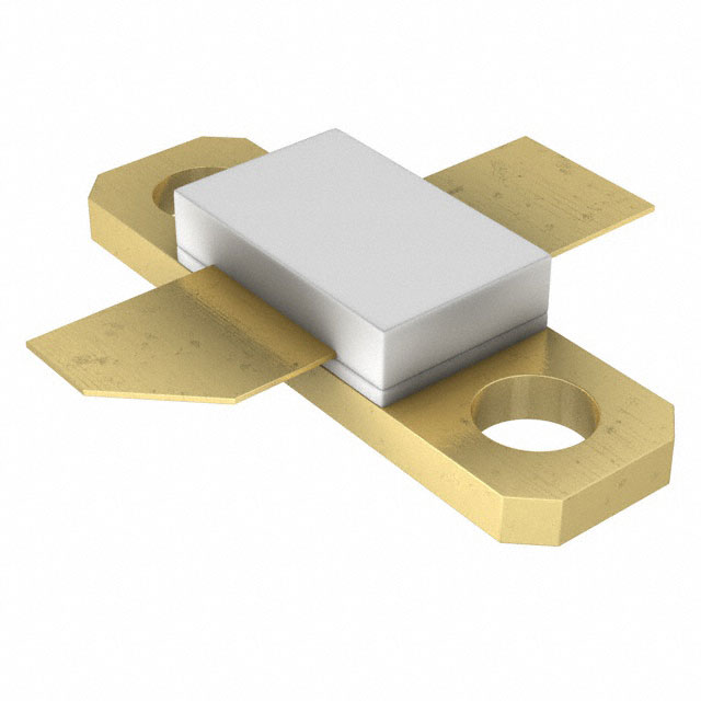
- Package Type: Metal-Ceramic
- Operating Voltage: 28 V
- Efficiency: 40%
Detailed Pin Configuration
The MRF21010LR1 features a 3-pin configuration: 1. Pin 1: RF Input 2. Pin 2: Ground 3. Pin 3: RF Output
Functional Features
- High Power Gain: Provides significant amplification of input RF signals.
- High Efficiency: Minimizes power loss during signal amplification.
- Excellent Linearity: Ensures faithful reproduction of input signals without distortion.
Advantages and Disadvantages
Advantages
- High power gain
- High efficiency
- Excellent linearity
- Reliable metal-ceramic packaging
Disadvantages
- Limited frequency range
- Higher cost compared to some alternative models
Working Principles
The MRF21010LR1 operates based on the principles of RF amplification. When an RF signal is applied to the input pin, the transistor amplifies the signal with high gain and efficiency, delivering an amplified output signal at the RF output pin. The transistor's linearity ensures that the amplified signal faithfully represents the input signal.
Detailed Application Field Plans
The MRF21010LR1 is widely used in the following applications: - Cellular base stations - Wireless communication systems - Radar systems - RF test equipment
Detailed and Complete Alternative Models
Some alternative models to the MRF21010LR1 include: - MRF21030LR5: Offers higher output power and wider frequency range. - MRF21120LR3: Provides lower power gain but operates at a higher frequency range.
In conclusion, the MRF21010LR1 is a high-performance RF power transistor suitable for various high-frequency applications, offering high power gain, efficiency, and linearity. Its reliable metal-ceramic packaging and detailed specifications make it a preferred choice for RF power amplifier circuits.
Word Count: 346
Noem 10 veelgestelde vragen en antwoorden met betrekking tot de toepassing van MRF21010LR1 in technische oplossingen
What is the MRF21010LR1?
- The MRF21010LR1 is a high-power RF transistor designed for use in applications such as industrial, scientific, and medical (ISM) equipment, as well as broadcast and aerospace systems.
What is the maximum power output of the MRF21010LR1?
- The MRF21010LR1 can deliver up to 100 watts of power output in the frequency range of 2110-2170 MHz.
What are the typical applications of the MRF21010LR1?
- Typical applications include cellular base station amplifiers, repeaters, and other high-power RF amplifiers used in wireless infrastructure.
What is the operating voltage and current of the MRF21010LR1?
- The MRF21010LR1 operates at a voltage range of 12-28 volts and typically draws a current of 1.5-3.0 amperes.
What are the key features of the MRF21010LR1?
- The MRF21010LR1 features high gain, high efficiency, and excellent linearity, making it suitable for demanding RF power amplifier applications.
What are the thermal considerations for using the MRF21010LR1?
- Proper heat sinking and thermal management are essential for maximizing the performance and reliability of the MRF21010LR1 in high-power applications.
What are the recommended biasing and matching circuits for the MRF21010LR1?
- The datasheet for the MRF21010LR1 provides detailed guidance on biasing and matching circuits to ensure optimal performance in specific applications.
What precautions should be taken when handling and mounting the MRF21010LR1?
- Care should be taken to avoid electrostatic discharge (ESD) and proper mounting techniques should be followed to minimize mechanical stress on the device.
What are the typical failure modes of the MRF21010LR1?
- Common failure modes include overvoltage, overcurrent, and excessive thermal stress, which can be mitigated through proper design and operational practices.
Where can I find additional technical support and resources for the MRF21010LR1?
- Technical support, application notes, and reference designs for the MRF21010LR1 are available from the manufacturer's website and authorized distributors.