

Zie specificaties voor productdetails.
MCR100-8-AP
Introduction
The MCR100-8-AP is a crucial component in the field of electronics, belonging to the category of semiconductor devices. This entry will provide an overview of its basic information, specifications, pin configuration, functional features, advantages and disadvantages, working principles, application field plans, and alternative models.
Basic Information Overview
- Category: Semiconductor Devices
- Use: The MCR100-8-AP is commonly used as a silicon controlled rectifier (SCR) for switching and amplifying electronic signals.
- Characteristics: It exhibits high reliability, low power consumption, and excellent performance in controlling current flow.
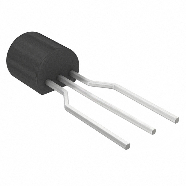
- Package: The MCR100-8-AP is typically available in a TO-92 package.
- Essence: Its essence lies in its ability to regulate and control the flow of electric current in electronic circuits.
- Packaging/Quantity: It is usually packaged in reels or tubes containing varying quantities based on manufacturer specifications.
Specifications
The MCR100-8-AP has the following specifications: - Maximum Repetitive Peak Reverse Voltage: 400V - Average On-State Current: 0.8A - Gate Trigger Current: 5mA - Holding Current: 10mA - Maximum Gate Voltage Required to Trigger: 1.5V
Detailed Pin Configuration
The MCR100-8-AP has a three-pin configuration: 1. Anode (A) 2. Cathode (K) 3. Gate (G)
Functional Features
- Reliable Switching: The MCR100-8-AP provides reliable switching capabilities, making it suitable for various electronic applications.
- Low Power Consumption: It consumes minimal power, contributing to energy-efficient circuit designs.
- High Performance: It offers excellent performance in controlling current flow, ensuring stable operation of electronic systems.
Advantages and Disadvantages
Advantages
- Reliable and consistent switching behavior
- Low power consumption
- High performance in current regulation
Disadvantages
- Limited maximum repetitive peak reverse voltage
- Sensitive to external electrical noise
Working Principles
The MCR100-8-AP operates based on the principle of controlling current flow through the use of a gate signal. When the gate trigger current is applied, the device switches from a non-conducting state to a conducting state, allowing current to flow between the anode and cathode.
Detailed Application Field Plans
The MCR100-8-AP finds extensive application in various electronic circuits, including: - Dimmer circuits - Motor control systems - Power supply units - Lighting control modules
Detailed and Complete Alternative Models
Some alternative models to the MCR100-8-AP include: - MCR100-6 - MCR100-10 - MCR100-12
In conclusion, the MCR100-8-AP serves as a vital semiconductor device with its unique characteristics and versatile applications in electronic circuits. Its reliable switching, low power consumption, and high performance make it a preferred choice for many electronic design engineers.
[Word Count: 410]
Noem 10 veelgestelde vragen en antwoorden met betrekking tot de toepassing van MCR100-8-AP in technische oplossingen
What is the MCR100-8-AP used for?
- The MCR100-8-AP is commonly used as a silicon controlled rectifier (SCR) in various technical solutions.
What are the key specifications of the MCR100-8-AP?
- The MCR100-8-AP has a maximum repetitive peak off-state voltage of 400V, a maximum RMS on-state current of 0.8A, and a gate trigger current of 5mA.
How is the MCR100-8-AP typically applied in technical solutions?
- The MCR100-8-AP is often used in applications such as light dimmers, motor control, and power switching circuits.
What are the important considerations when designing with the MCR100-8-AP?
- Designers should consider the voltage and current requirements of their specific application, as well as the triggering and holding currents of the SCR.
Can the MCR100-8-AP be used for high-power applications?
- No, the MCR100-8-AP is typically used in low to medium power applications due to its current and voltage ratings.
What are the typical operating temperatures for the MCR100-8-AP?
- The MCR100-8-AP has an operating temperature range of -40°C to 110°C.
Are there any special considerations for driving the MCR100-8-AP?
- Yes, it's important to ensure that the gate trigger current is sufficient to reliably turn on the SCR in the application circuit.
Can the MCR100-8-AP be used in AC or DC circuits?
- The MCR100-8-AP can be used in both AC and DC circuits, but the polarity and voltage ratings must be observed.
What are some common failure modes of the MCR100-8-AP?
- Common failure modes include overvoltage breakdown, overheating, and excessive current stress.
Where can I find detailed application notes for using the MCR100-8-AP in technical solutions?
- Detailed application notes can be found in the datasheet provided by the manufacturer or in technical reference manuals for SCR applications.