

Zie specificaties voor productdetails.
IRS2104SPBF
Product Overview
Category
The IRS2104SPBF belongs to the category of integrated circuits (ICs) specifically designed for power management applications.
Use
This IC is commonly used in various power electronics systems, such as motor drives, inverters, and switch-mode power supplies.
Characteristics
- The IRS2104SPBF is a high voltage, high-speed power MOSFET and IGBT driver.
- It operates with a wide input voltage range, making it suitable for different power supply designs.
- This IC provides protection features like under-voltage lockout (UVLO) and over-current protection (OCP).
- It offers low propagation delay and fast rise/fall times, ensuring efficient switching performance.
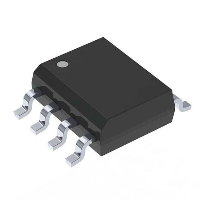
Package
The IRS2104SPBF is available in a small outline package (SOP) with 8 pins. This package type allows for easy integration into circuit boards.
Essence
The essence of the IRS2104SPBF lies in its ability to drive power MOSFETs and IGBTs effectively, enabling efficient power conversion and control in various applications.
Packaging/Quantity
The IRS2104SPBF is typically packaged in reels or tubes, containing a specific quantity of ICs per package. The exact quantity may vary depending on the manufacturer's specifications.
Specifications
- Input Voltage Range: 10V - 20V
- Output Current: 200mA
- Operating Temperature Range: -40°C to +125°C
- Supply Voltage Range: 10V - 20V
- Maximum Propagation Delay: 100ns
- Maximum Rise/Fall Time: 25ns
Detailed Pin Configuration
- VCC: Power supply voltage input
- HO: High-side gate driver output
- LO: Low-side gate driver output
- COM: Common connection for the high-side and low-side drivers
- VB: Bootstrap supply voltage input
- VS: High-side floating supply voltage input
- HS: High-side floating supply return
- LS: Low-side floating supply return
Functional Features
- High voltage level shifting capability for driving power MOSFETs and IGBTs.
- Integrated under-voltage lockout (UVLO) protection to prevent improper operation during low voltage conditions.
- Over-current protection (OCP) feature to safeguard against excessive current flow.
- Fast switching speed and low propagation delay for efficient power conversion.
Advantages and Disadvantages
Advantages
- Wide input voltage range allows for versatile application in different power supply designs.
- Efficient power MOSFET and IGBT driving capabilities ensure optimal performance.
- Integrated protection features enhance system reliability and safety.
- Compact SOP package enables easy integration into circuit boards.
Disadvantages
- Limited output current may restrict usage in high-power applications.
- Requires external bootstrap supply voltage for proper operation.
Working Principles
The IRS2104SPBF operates by receiving input signals from a control circuit and generating corresponding gate drive signals for power MOSFETs or IGBTs. It utilizes high voltage level shifting techniques to provide the necessary drive voltage levels required by these devices. The IC also incorporates protection features like UVLO and OCP to ensure safe and reliable operation.
Detailed Application Field Plans
The IRS2104SPBF finds extensive use in various power electronics applications, including: 1. Motor Drives: Controlling the speed and direction of motors in industrial automation systems. 2. Inverters: Converting DC power to AC power in renewable energy systems and motor drives. 3. Switch-Mode Power Supplies: Regulating and converting electrical power efficiently in electronic devices.
Detailed and Complete Alternative Models
- IRS2101SPBF: Similar to IRS2104SPBF, but with a single high-side gate driver output.
- IRS2103SPBF: Similar to IRS2104SPBF, but without the over-current protection feature.
- IRS21844SPBF: Dual channel MOSFET and IGBT driver with additional features like deadtime control.
Note: This is not an exhaustive list of alternative models, and it is recommended to consult the manufacturer's documentation for a complete range of options.
Word count: 590 words
Noem 10 veelgestelde vragen en antwoorden met betrekking tot de toepassing van IRS2104SPBF in technische oplossingen
Sure! Here are 10 common questions and answers related to the application of IRS2104SPBF in technical solutions:
Q: What is IRS2104SPBF? A: IRS2104SPBF is a high-speed, high-voltage MOSFET and IGBT driver IC designed for applications requiring high current and voltage drive capability.
Q: What is the maximum supply voltage for IRS2104SPBF? A: The maximum supply voltage for IRS2104SPBF is typically 600V.
Q: Can IRS2104SPBF be used with both MOSFETs and IGBTs? A: Yes, IRS2104SPBF can be used with both MOSFETs and IGBTs as it provides high current and voltage drive capability for both types of devices.
Q: What is the maximum output current of IRS2104SPBF? A: The maximum output current of IRS2104SPBF is typically 290mA.
Q: Is IRS2104SPBF suitable for high-frequency applications? A: Yes, IRS2104SPBF is suitable for high-frequency applications as it has a high-speed switching capability.
Q: Does IRS2104SPBF have built-in protection features? A: Yes, IRS2104SPBF has built-in protection features such as under-voltage lockout (UVLO), over-current protection (OCP), and thermal shutdown.
Q: What is the recommended operating temperature range for IRS2104SPBF? A: The recommended operating temperature range for IRS2104SPBF is typically -40°C to +125°C.
Q: Can IRS2104SPBF be used in automotive applications? A: Yes, IRS2104SPBF is suitable for automotive applications as it meets the necessary automotive standards and has a wide operating temperature range.
Q: What is the typical propagation delay of IRS2104SPBF? A: The typical propagation delay of IRS2104SPBF is around 100ns.
Q: Can IRS2104SPBF be used in bridge driver configurations? A: Yes, IRS2104SPBF can be used in bridge driver configurations as it provides two complementary outputs for driving the high-side and low-side devices in a bridge configuration.
Please note that the answers provided here are general and may vary depending on specific datasheet specifications and application requirements.